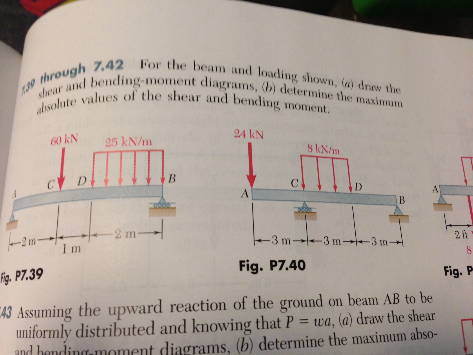
Answer to 739 through 742 for the beam and loading shown a draw the shear and bending moment diagrams b determine the maxi. For teachers for schools for working scholars.

Shear Force And Bending Moment Diagram Practice Problem 1

Analysis And Design Of Beams For Bending

English Finding Shear Force And Bending Moment Equations For A Simple Beam
25 knm18 m 45 kn.
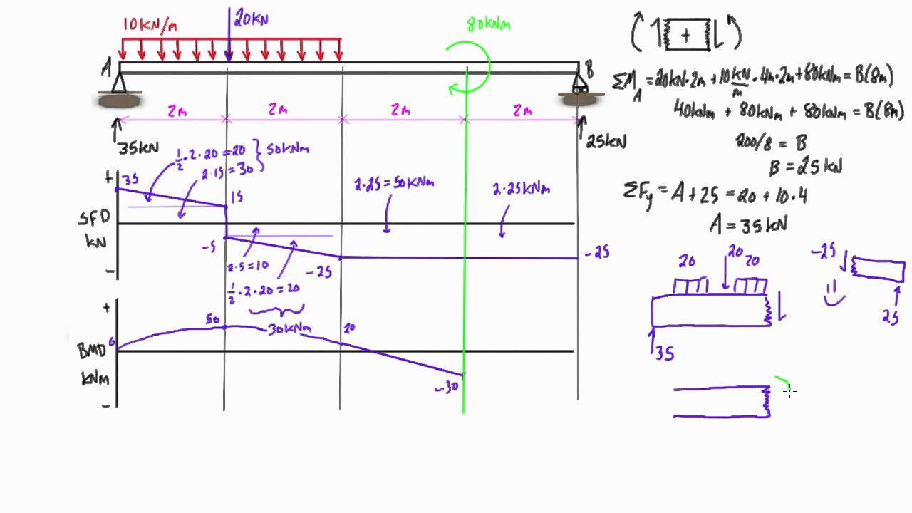
Draw the shear and moment diagrams for the beam and loading shown and determine the maximum.
Draw the shear and bending moment diagrams for the beam and loading shown and determine the maximum absolute value.
Solution the distributed load is replaced with an equivalent concentrated load of 45 kn to compute the reactions.
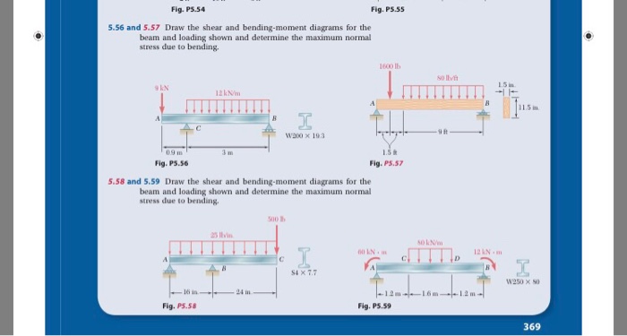
Answer to draw the shear and bending moment diagrams for the beam and loading shown and determine the maximum normal stress due.
Shear force and bending moment diagram for simply supported beam with udl duration.
These diagrams are usually discontinuous or have discontinuous slopes.
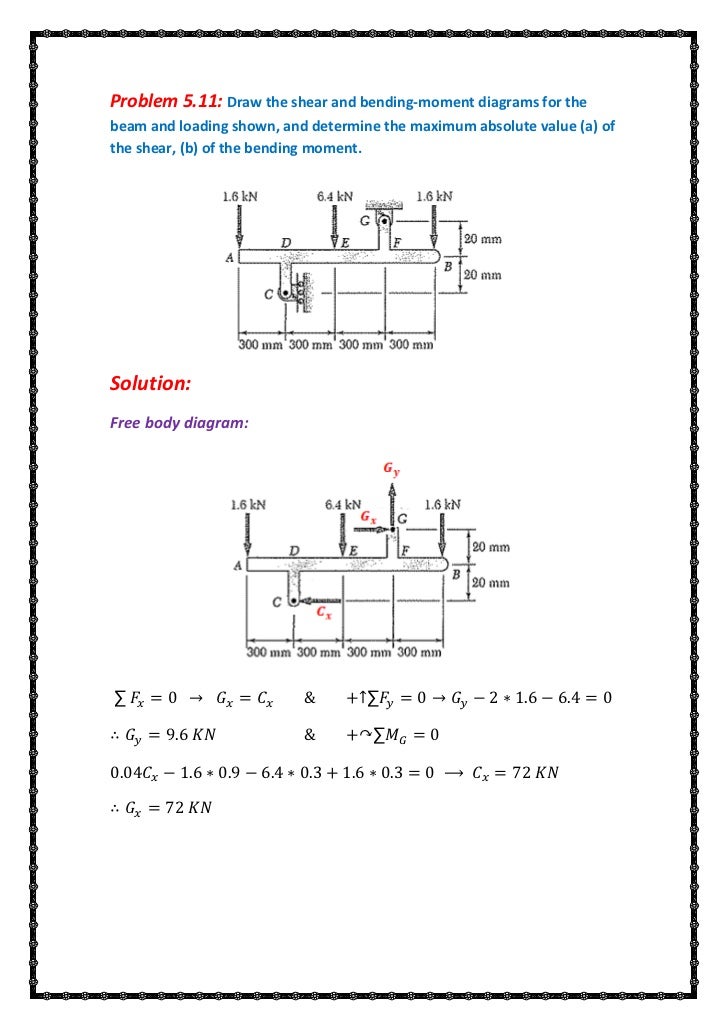
B determine the maximum absolute values.
Draw the shear and bending moment diagrams for the beam and loading shown and determine the maximum absolute value a of the shear b of the bending moment.
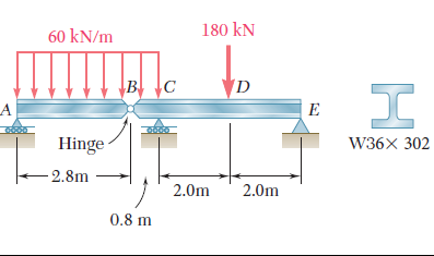
For the beam and loading shown in the figure a draw the shear and bending moment diagrams.
100 23 ratings.
Draw the shear and bending moment diagrams for the beam and loading shown and determine the maximum absolute value a of the shear b of the bending moment.
A of the shear b of the bending moment c the distance x from point a where this bending moment occurs.
At the end points of the segments due to discontinuities in loading.
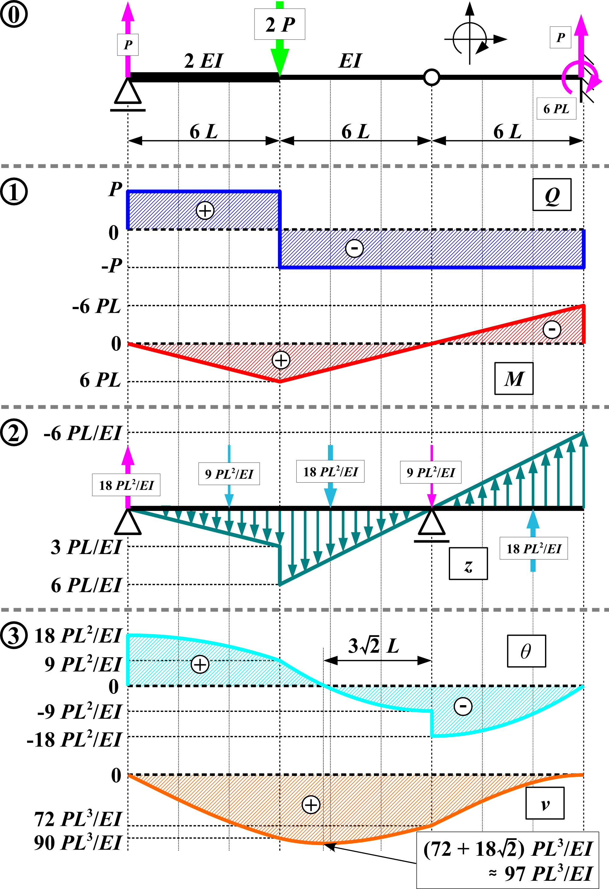
For the beam and loading shown a draw the shear and bending moment diagrams b determine the equations of the shear and bending moment curves.
The bending moment and shear force diagrams of the beam are composites of the v and m diagrams of the segments.
Show transcribed image text draw the shear and bending moment diagrams for the beam and loading shown and determine the maximum normal stress due to bending.
Beam and then draw the m diagrambelow the v diagram.
Care 4 education 757288 views.
Draw the shear and bending moment diagrams for the beam and loading shown and determine the maximum normal stress due to bending.
Chapter 06 Solution Manual Mechanics Of Materials Mom
Chapter 06 Solution Manual Mechanics Of Materials Mom
Problem 5 1
Solved For The Beam And Loading Shown A Draw The Shear
Untitled
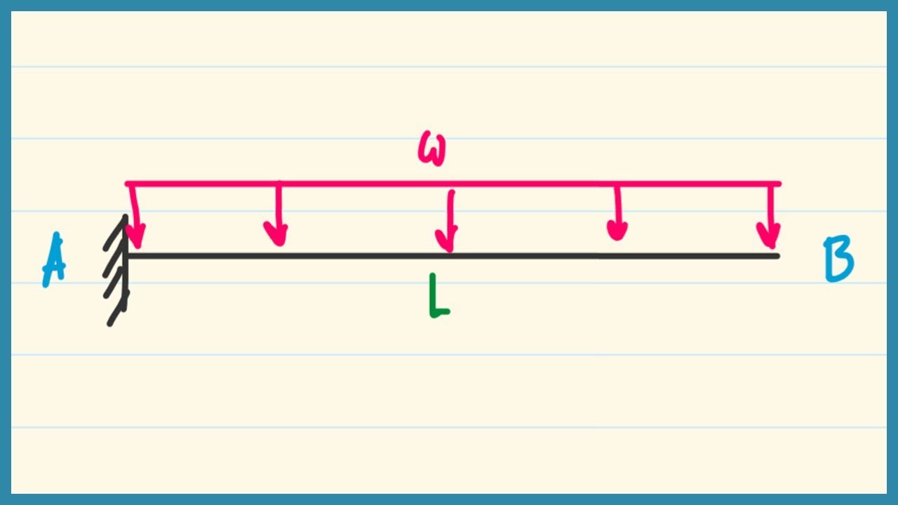
Ex 07 Shear Moment Diagram Cantilever Beam Distributed Load Part I

Analysis And Design Of Beams For Bending
Chapter 06 Solution Manual Mechanics Of Materials Mom

Pdf Solver Nestor Cardona Academia Edu
Solved Draw The Shear And Bending Moment Diagrams For The
Problem 5 1

For The Beam And Loading Shown Draw The Shear V And Bending

How To Calculate And Draw Shear And Bending Moment Diagrams

How To Calculate And Draw Shear And Bending Moment Diagrams
Solved Draw The Shear And Bending Moment Diagrams For The
Untitled

How To Draw Shear Force And Bending Moment Diagrams

Analysis And Design Of Beams For Bending

For The Beam And Loading Shown A Draw The Shear And
Chapter 06 Solution Manual Mechanics Of Materials Mom
Problem 5 1

Analysis And Design Of Beams For Bending

Problem Lb Ft For The Beam And Loading Shown A Draw The
Solved For The Beam And Loading Shown Below A Evaluate
Shear Force And Bending Moment Diagram Practice Problem 9
Conjugate Beam Method Wikipedia
Problem 5 1
Problem 5 1

Hibbeler Statics Solution Chapter 7 1

For The Beam And Loading Shown Determine The Reaction At

Determine The Normal Shear Force And Bending Moment At C And D
Mechanics Of Materials Chapter 4 Shear And Moment In Beams

Analysis And Design Of Beams For Bending
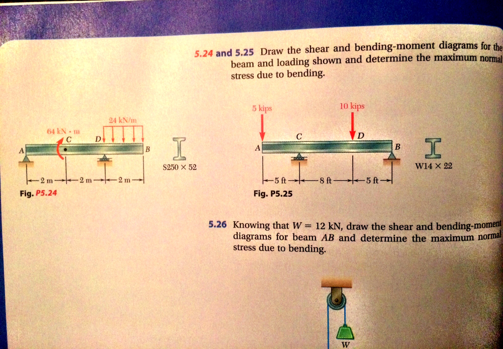
Solved 5 24 And 5 25 Draw The Shear And Bending Moment Di
Untitled

Beam Reactions And Diagrams Strength Of Materials

Mechanics Of Materials 7th Edition Beer Johnson Chapter 5
Ch 5 Problems
No comments:
Post a Comment