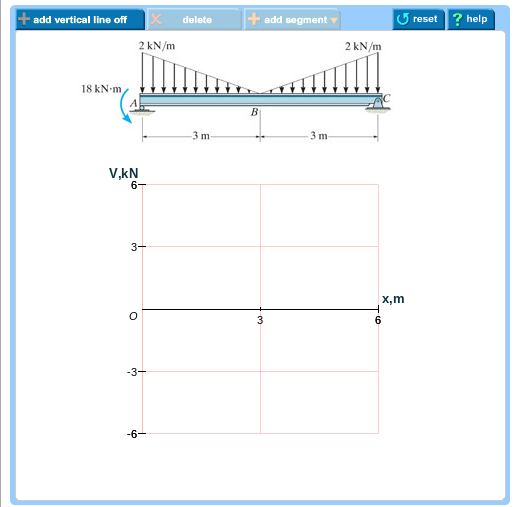
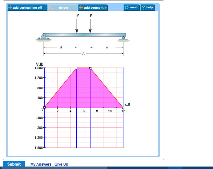
Then click on add segment button to add functions between the lines. Click on add discontinuity to add discontinuity lines.

Pdf Solution Manual 7a Fatin Lyana Jimmy Academia Edu
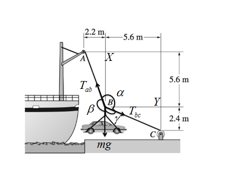
The 1200 Kg Car Is Being Lowered Slowly Onto The Dock Using

Sensitivity And Uncertainty Analysis Of Aar Affected
Use symmetry to evaluate.

Draw the shear diagram for the beam set p 800 lb a 5 ft l 12 ft.
B set p800lb a5ft l12ft.
Click on add discontinuity to add discontinuity lines.
Draw the shear diagram for the beam.
B set p 800 lb a 5 ft l 12 ft.
200lb 100lb 250lb 100lb 0 250 lbrc at any point v is the sum of the loads and reactions to the left assuming and m the sum of their moments about that point assuming.
45in 100 lb15in 250 lb20 in 100 lb55in 0r 200 lbre fryc0.
The engine crane is used to support the engine which has a weight of 1200 lb.
Mxx 15 6 9 kip ft2 atd x 6 ft vm12 kips 27 kip ft d to b.
B set p 800 lb.
Draw the shear and moment diagrams for the beam a in termsof the parameters shown.
Set p 800 lb a 5 ft l 12 ft.
Get this answer with chegg study.
Click on add discontinuity to add discontinuity lines.
Then click on add segment button to add functions between the lines.
L 12 ft.
Draw the shear and bending moment diagrams for the beam a in terms of parameters shown.
Draw the shear and bending moment diagrams for the beam a in terms of the parameters shown.
Draw the moment diagram for the beam.
Draw the moment diagram for the beam.
A 5 ft l 12 ft.
3 ft 5 ft b c.
Set p 800 lb a 5 ft.
Show transcribed image text draw the shear and moment diagrams for the beam a in terms of the parameters shown.
Assuming that the reaction of the ground is uniformly distributed draw the shear and bending moment diagrams for the beam ab and determine the maximum absolute value a of the shear b of the bending moment.
Get more help from chegg get 11 help now from expert mechanical engineering tutors.
3 ft 3 ft 200 lbft 400 lb 6 ft 400 lb a b m lb ft x ft v lb 0 400 0 12 x ft 600 1200 1200 300 600 400 3 6 369 12 9 ans.
B set p 800 lb a 5 ft l 12 ft.
Draw the shear and moment diagrams of the boom abcwhen it is in the horizontal position shown.
Hibbelerchapter 6part 1 487 517qxd 21213 1107 am page 499.
Draw the shear and moment diagrams for the double overhanging beam.
Set p 800 lb a 5 ft l 12 ft.

Mechanics Of Materials 7th Edition Beer Johnson Chapter 5
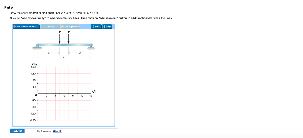
Solved Part A Draw The Shear Diagram For The Beam Set P

Seismic Response Evaluation Of The Linked Column Frame

Philpot Mom 2nd Ch07 11 Ism Bending Beam Structure
Ch 7 Solution Manual Engineering Mechanics Statics

Performance Based Structural Fire Engineering Of Steel
Chapter 06 Solution Manual Mechanics Of Materials Mom

Shear And Moment Diagrams Example
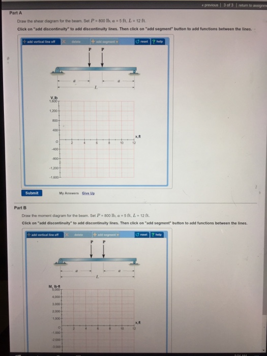
Solved Draw The Shear Diagram For The Beam Set P 800 L

Hibbeler Statics Solution Chapter 7 1

Hibbeler Statics Solution Chapter 7 1
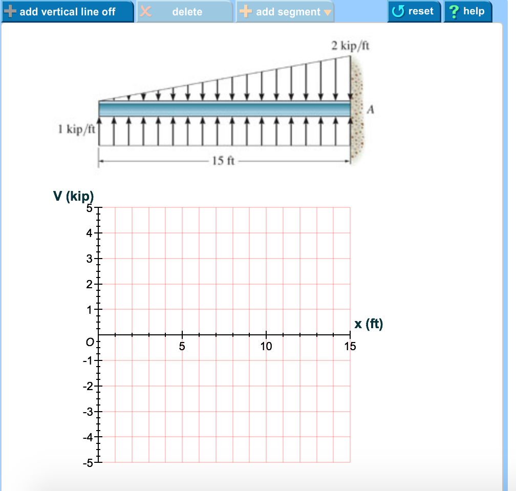
Draw The Shear Diagram For The Beam Wiring Diagram All
Draw The Shear Diagram For The Beam Wiring Diagram All
Chapter 06 Solution Manual Mechanics Of Materials Mom
Solution

Draw The Shear And Bending Moment Diagrams For The Beam A

V M Diagrams Bending Beam Structure

Draw The Shear And Bending Moment Diagrams For The Beam Set

Solved Draw The Shear And Moment Diagrams For The Beam A
Risa Structural Analysis Design

Hibbeler Statics Solution Chapter 7 1
Solution

Seismic Performance Of Circular Concrete Columns Reinforced

Pdf Chapter 06 Andres Hernandez Academia Edu

Determine The Intensities W1 And W2 Of This Distribution

Determine The Normal Force Shear Force And Moment At Point C

Hibbeler Statics Solution Chapter 7 1
Solution
Beams Springerlink
Risa Structural Analysis Design
Strength Of Materials

Hibbeler Statics Solution Chapter 7 1

Propped Cantilever An Overview Sciencedirect Topics
Chapter 06 Solution Manual Mechanics Of Materials Mom

Pdf Vector Mechanics For Engineers Chapter 07 Pdf Ziad
Solution

Hibbeler Statics 12 Ed Cap 7 2
Solved Plz Help In This Question Part A Draw The Shear D
No comments:
Post a Comment